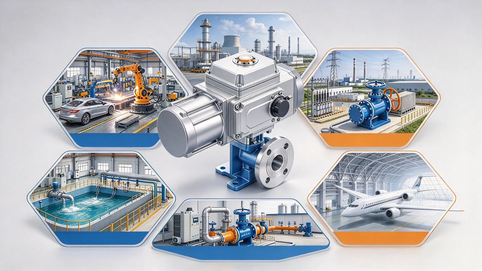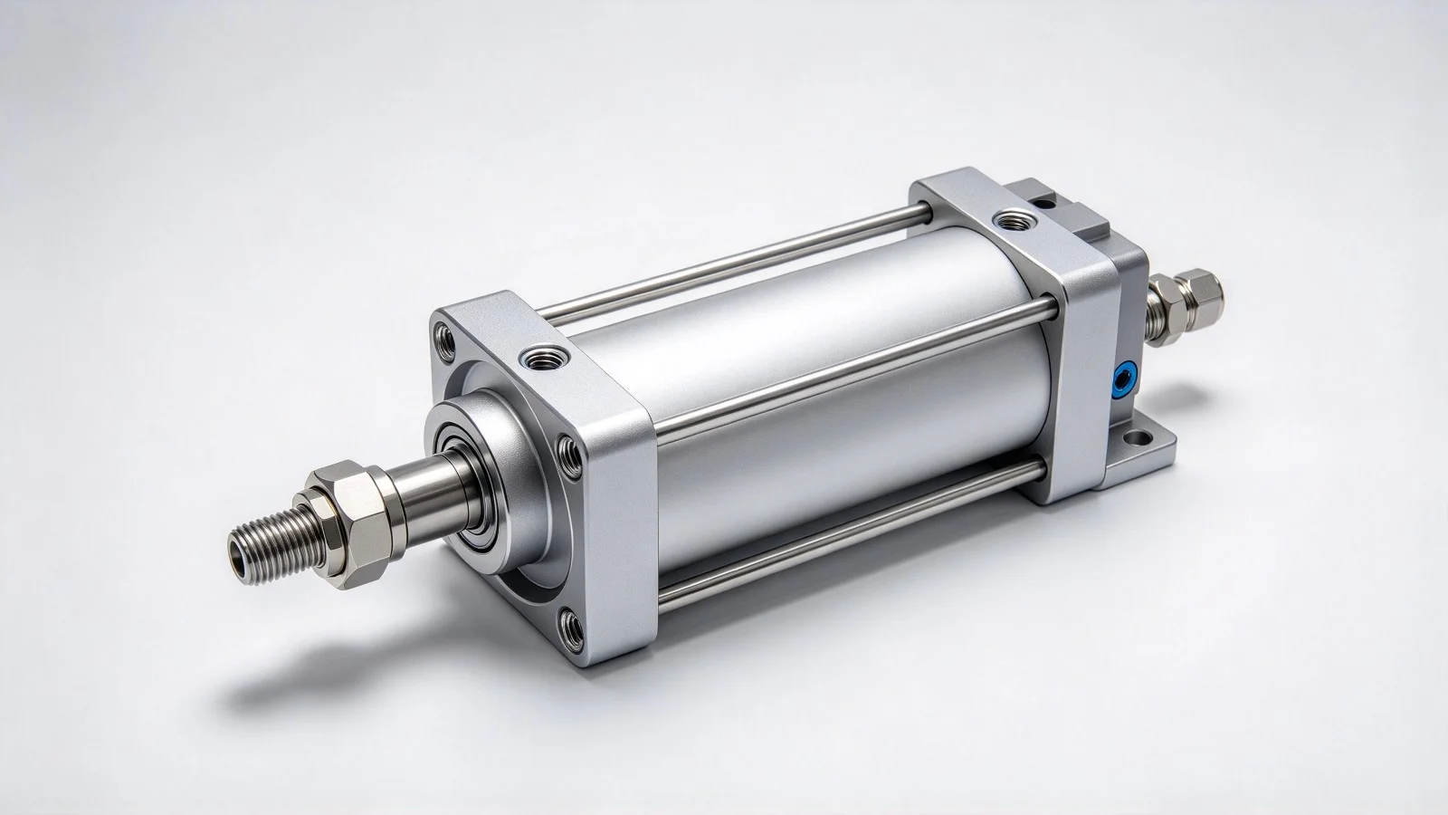
An electric actuator links control commands to valve movement. Its operating condition affects opening, closing and regulation. Failure to start, slow movement, interrupted operation or incomplete valve travel can arise from power supply, control signals, transmission components or the actual load.
Troubleshooting should follow the observed symptoms, progressing from electrical systems to mechanical components and avoiding unsupported adjustment or replacement.
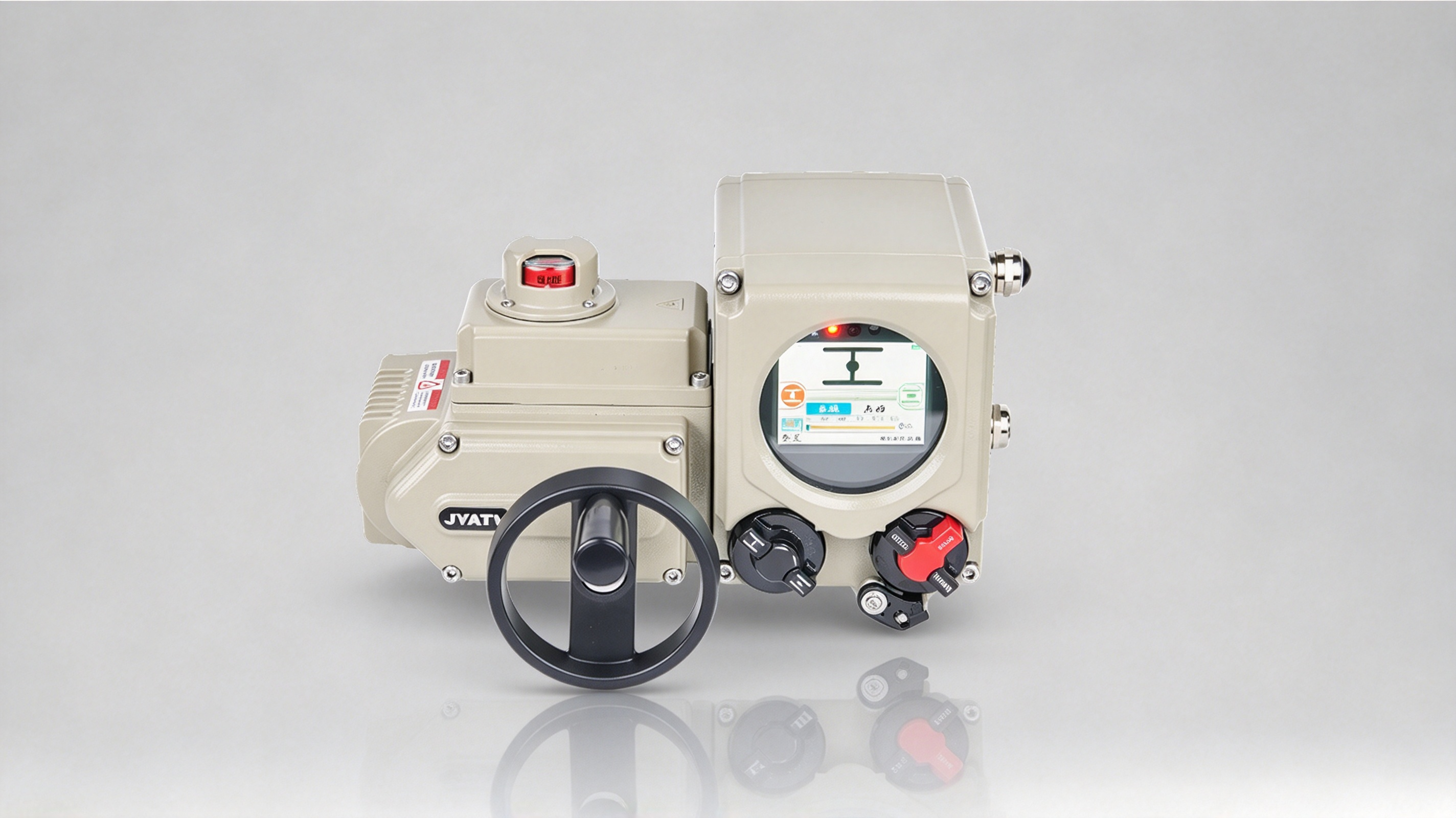
1. Check the power supply and electrical condition
- Verify the power supply
Abnormal voltage, phase loss or loose wiring can affect operation. Check that the supply voltage meets the equipment requirements and inspect wiring, terminals and protective devices. For three-phase actuators, check for phase loss.
- Check electrical protection
If the actuator stops immediately after starting, trips or raises an alarm, inspect overload, short-circuit and other protection records to identify electrical faults or abnormal loading. Correct the cause before restoring operation according to the equipment instructions; do not bypass protective functions.
2. Verify signals and control settings
- Check the control command
For remotely controlled actuators, confirm that the control system sends the required opening, closing or regulating command. Inspect control wiring, signal interfaces and connections. For analogue control, verify that the input signal is within the specified range.
- Verify the operating mode
Actuators may offer local, remote and automatic modes. If a command produces no response, check the selected mode, interlocks and operating permissions against the intended operation.
3. Inspect the transmission for mechanical faults
- Check the transmission mechanism
The motor and transmission transfer power to the valve. Worn, jammed or damaged gears and connecting components can cause slow movement, abnormal noise or incomplete travel. Inspect the mechanism according to the equipment design and arrange maintenance where required.
- Check the valve connection
Verify secure connections between actuator and valve, compatibility of the drive interface and correct mounting. Loose connections or incorrect assembly can interfere with power transfer and valve movement.
4. Verify the load and output capability
- Check valve operating resistance
For difficult movement, incomplete travel or overload shutdown, inspect the valve for sticking, deposits, foreign objects or other sources of increased resistance. Consider changes in valve loading under high pressure, high temperature or special-media conditions.
- Review actuator selection
If the valve has no obvious fault, confirm that actuator torque or thrust meets the operating requirement, including operating frequency, duty and site conditions. Reassess selection where output capability does not match the load, to avoid prolonged overload.
5. Check travel limits and position feedback
- Check travel limits
Incorrect travel-limit settings can stop the actuator before the valve is fully open or closed. Inspect opening and closing limits and feedback according to the actuator manual and valve requirements.
- Verify position feedback
If the indicated position differs from the actual valve position, inspect the position sensor, feedback wiring and settings for transmission or calibration problems. Follow the manufacturer's procedures so that adjustments do not compromise limit protection or safe valve operation.
Actuator faults may involve power supply, control, transmission, loading and position feedback. Start with power and control signals, then check the transmission and valve load, and finally confirm limits and feedback. A systematic assessment helps identify the cause and restore coordinated actuator and valve operation.